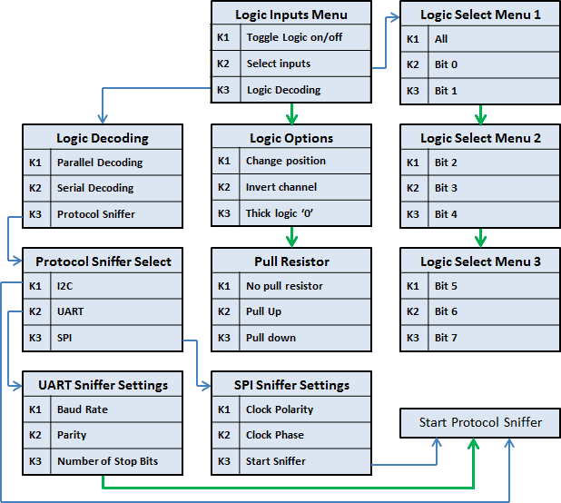
The Xprotolab has an 8 bit logic analyzer and can do sniffing on standard protocols: I2C, UART and SPI.
The logic inputs are 3.3V level. The Xprotolab logic inputs are not 5V tolerant!, If you need to connect 5V signals to the logic analyzer, you could:
Add a 3K resistor in series with the signal, or, use a 5V to 3.3V level converter chip.
Logic Analyzer Menu

Parallel Decoding
Shows the hexadecimal value of the 8 bit digital input lines. The hexadecimal number is shown below the last digital trace. If all the 8 digital traces are enabled, then there is no space to show the parallel decoding.
Serial Decoding
Shows the hexadecimal value of the stream of bits on each channel. The decoding starts at the first vertical cursor and ends at the second vertical cursor, 8 bits are decoded. If the cursors are disabled, then the decoding is done from the start of the screen, to the end.
Protocol Sniffers
When the Xprotolab is in Sniffer mode, a small text appears on the screen, indicating where to hook up the signals. As soon as the data is received, the data is displayed in "pages".
There are 16 pages of data. To browse thru the pages, use the buttons K2 and K3.
In the UART and SPI sniffers, the data can be displayed in HEX or ASCII, press K2 and K3 simultaneously to toggle between them.
If using ASCII, note that letters will be always uppercase, and only codes 0x20 thru 0x7A will show valid characters.
I2C Sniffer - Connect SDA to Bit 0, SCL to Bit 1
The Xprotolab implements the I2C sniffing in a bit-bang fashion. The maximum clock frequency is 400kHz (Standard I2C Fast Speed).
As the data is decoded, the data in HEX will appear on the screen, accompanied by a symbol:
When the Master initiates a read, < is an ACK and ( is a NACK
When the Master initiates a write, > is an ACK and ) is a NACK
Subsequent data in the frame will be accompanied by + for ACK or a - for NACK.
There are 16 pages of data, each page shows 64 bytes => the total memory for the I2C sniffer is 1024 bytes.
UART Sniffer - Connect RX to Bit 2, TX to Bit 3
The Xprotolab can decode both the TX and RX lines of the UART at the standard baud rates:
1200, 2400, 4800, 9600, 19200, 38400, 57600, 115200
The screen is split in two, the left side is use for the RX line, and the right side is used for the TX line. Each side can show 40 bytes per page. With 16 pages, a total of 640 bytes can be stored for each decoded line.
SPI Sniffer - Connect the Select to Bit 4, MOSI to Bit 5, MISO to Bit 6, SCK to Bit 7
The Xprotolab can decode both the MOSI and MISO lines of an SPI bus. The SPI's MOSI pin decoding is done in hardware, so it can decode data at high speed, But the SPI's MISO pin decoding is implemented in software using bit-banging, so the maximum clock allowed will be limited.
The screen is split in two, the left side is use for the MOSI line, and the right side is used for the MISO line. Each side can show 40 bytes per page. With 16 pages, a total of 640 bytes can be stored for each decoded line.

